・2014/08/01
 MicrochipのUSB内蔵PICマイコンで楽々USB機器開発 2014年版
(C言語で楽にUSB機器の開発ができます PIC24FJ64GB002 2014年版)
Tags: [ワンチップCPU]
● PICマイコンで USB周辺機器を作る
久しぶりに PICマイコンを使った電子工作をする事になりました。
以前、PICマイコンで USB関係の機器を開発したのが 2005/07/18なので 9年ぶりに電子工作をする事になります。
PICマイコンとしては手軽に購入でき、WEB上で開発例が多い品種を選定します。
・PIC18F14K50
秋月 PIC18F14K50使用USB対応超小型マイコンボード
[K-05499] PIC18F14K50使用USB対応超小型マイコンボード
1個 ¥800(税込)
製作例:
はじめての PIC PIC18F14K50
・PIC18F26J50
秋月 PICマイコンPIC18F26J50-I/SP
[I-05396] PICマイコンPIC18F26J50-I/SP
1個 ¥260(税込)
製作例:
はじめての PIC PIC18F26J50
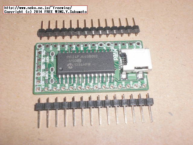
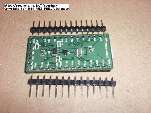
・PIC24FJ64GB002
マイボードの小部屋 PICマイコン 電子工作 PIC24FJ64GB002 PIC18F14K50
の中で扱いのある
PIC24FJ64GB002マイコンボード
がヤフオクから 1200円(送料無料)で購入できます。
2016/10 追記:現在はヤフオクに出品していない模様。PIC24FJ64GB002ボードをもっと買っておけば良かった。
製作例:
マイボードの小部屋 PIC24FJ64GB002
サンプルプログラムの ZIPファイルの解凍にはヤフオクで購入後のパスワードが必要。
PICマイコンの参考書
「PIC マイコン」 を Amazonで探す(商品検索する)。
「PIC マイコン USB」を Amazonで探す(商品検索する)。
●はじめに
とりあえず、秋月の PIC18F14K50使用USB対応超小型マイコンボードを購入し、サンプルをコンパイルして動かす事で忘れていた昔の記憶を呼び覚まします。
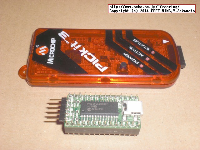
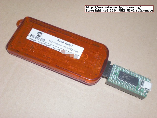
また、PICの書き込みには PIC WRITERが必要で今回は会社に転がっている Pickit3(PIC KIT3)を使用しました。
PICkit3は 秋月で 4300円で売っています。
秋月 マイクロチップ PICkit3
PICkit 3 In-Circuit Debugger Part Number: PG164130
●開発方法
以下編集中
2016/10 追記:久々に必要が生じたのでまとめ。
PIC24FJ64GB002
MPLAB X Integrated Development Environment (IDE)
MPLAB X統合開発環境(IDE)
MPLAB X IDE v3.40 9/2/2016 557.5MB
MPLAB X v2.35 369MB
MPLAB XC Compilers
MPLAB XC16 Compiler v1.26
PIC24FJ64GB002は XC16 Compiler
C:\Program Files (x86)\Microchip\xc16\v1.26
Microchip Libraries for Applications
Microchipアプリケーション用ライブラリ(MLA)
バージョン毎にディレクトリ構成やアプリの構造が異なる。
v2015-08-10 Windows Microchip Libraries for Applications
MLAの最新は 2016/04/27らしいが、何故か公式ページから消えている。
mla_v2016_04_27_windows_installer.exe インストールパッケージの直リンク
http://ww1.microchip.com/downloads/en/softwarelibrary/mla_v2016_04_27_windows_installer.exe
MPLAB Harmony Integrated Software Framework
MPLAB Harmony Integrated Software Framework v1.08.01
PIC32シリーズ用、最近出てきた新しいフレームワーク?
Code Examples
● とりあえず作ってみたテスト
Android ADK, ADB-Bridge, USB Keyboard等のサンプルが動きました。
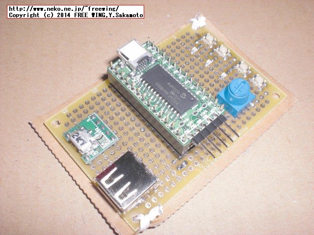
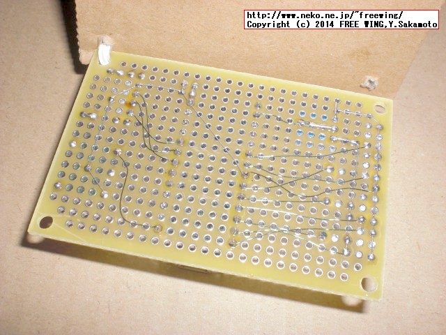
・PIC24FJ64GB002ボードを使用した作品例

・PIC24FJ64GB002ボードを使用した作品例
・PIC24FJ64GB002ボードを使用した作品例
・PIC24FJ64GB002ボードを使用した作品例 PICkit3接続方法
・PIC24FJ64GB002ボードを使用した作品例
・PIC24FJ64GB002ボードを使用した作品例
● LEDをチカチカ、通称Lチカ/エルチカ
以下編集中
2016/10 追記:久々に必要が生じたのでいじくった所、全く動かなくてはまったのでメモ。
はまりどころ。(2014年の時と同じ所でハマりました)
「マイボードの小部屋」の PIC24FJ64GB002ボードを使用する場合。
●マイコンボードが動かない場合。
オシレーター関係の設定(内部オシレータ使用)
最近は _CONFIG1(XXX)構文ではなく、
#pragma config
構文を使って定義する。
「マイボードの小部屋」の PIC24FJ64GB002ボードを使用する場合の #pragma configの設定内容。
 /** CONFIGURATION Bits **********************************************/
 // CONFIG4
#pragma config DSWDTPS = DSWDTPS3       // DSWDT Postscale Select (1:128 (132 ms))
#pragma config DSWDTOSC = LPRC    // Deep Sleep Watchdog Timer Oscillator Select (DSWDT uses Low Power RC Oscillator (LPRC))
 //#pragma config RTCOSC = SOSC      // RTCC Reference Oscillator Select (RTCC uses Secondary Oscillator (SOSC))
#pragma config RTCOSC = LPRC      // RTCC Reference Oscillator Select (RTCC uses Secondary Oscillator (SOSC))
#pragma config DSBOREN = OFF      // Deep Sleep BOR Enable bit (BOR disabled in Deep Sleep)
#pragma config DSWDTEN = OFF      // Deep Sleep Watchdog Timer (DSWDT disabled)

 // CONFIG3
#pragma config WPFP = WPFP0       // Write Protection Flash Page Segment Boundary (Page 0 (0x0))
 //#pragma config SOSCSEL = SOSC     // Secondary Oscillator Pin Mode Select (SOSC pins in Default (high drive-strength) Oscillator Mode)
#pragma config SOSCSEL = IO       // Secondary Oscillator Pin Mode Select (SOSC pins in Default (high drive-strength) Oscillator Mode)
#pragma config WUTSEL = LEG       // Voltage Regulator Wake-up Time Select (Default regulator start-up time used)
#pragma config WPDIS = WPDIS      // Segment Write Protection Disable (Segmented code protection disabled)
#pragma config WPCFG = WPCFGDIS         // Write Protect Configuration Page Select (Last page and Flash Configuration words are unprotected)
#pragma config WPEND = WPENDMEM         // Segment Write Protection End Page Select (Write Protect from WPFP to the last page of memory)

 // CONFIG2
 //#pragma config POSCMOD = HS       // Primary Oscillator Select (HS Oscillator mode selected)
#pragma config POSCMOD = NONE       // Primary Oscillator Select (HS Oscillator mode selected)
#pragma config I2C1SEL = PRI      // I2C1 Pin Select bit (Use default SCL1/SDA1 pins for I2C1 )
#pragma config IOL1WAY = OFF      // IOLOCK One-Way Set Enable (The IOLOCK bit can be set and cleared using the unlock sequence)
#pragma config OSCIOFNC = ON      // OSCO Pin Configuration (OSCO pin functions as port I/O (RA3))
 //#pragma config FCKSM = CSDCMD     // Clock Switching and Fail-Safe Clock Monitor (Sw Disabled, Mon Disabled)
#pragma config FCKSM = CSECME     // Clock Switching and Fail-Safe Clock Monitor (Sw Disabled, Mon Disabled)
 //#pragma config FNOSC = PRIPLL     // Initial Oscillator Select (Primary Oscillator with PLL module (XTPLL, HSPLL, ECPLL))
#pragma config FNOSC = FRCPLL     // Initial Oscillator Select (Primary Oscillator with PLL module (XTPLL, HSPLL, ECPLL))
#pragma config PLL96MHZ = ON      // 96MHz PLL Startup Select (96 MHz PLL Startup is enabled automatically on start-up)
#pragma config PLLDIV = DIV2      // USB 96 MHz PLL Prescaler Select (Oscillator input divided by 2 (8 MHz input))
#pragma config IESO = OFF         // Internal External Switchover (IESO mode (Two-Speed Start-up) disabled)

 // CONFIG1
#pragma config WDTPS = PS1        // Watchdog Timer Postscaler (1:1)
#pragma config FWPSA = PR32       // WDT Prescaler (Prescaler ratio of 1:32)
#pragma config WINDIS = OFF       // Windowed WDT (Standard Watchdog Timer enabled,(Windowed-mode is disabled))
#pragma config FWDTEN = OFF       // Watchdog Timer (Watchdog Timer is disabled)
#pragma config ICS = PGx1         // Emulator Pin Placement Select bits (Emulator functions are shared with PGEC1/PGED1)
#pragma config GWRP = OFF         // General Segment Write Protect (Writes to program memory are allowed)
#pragma config GCP = OFF          // General Segment Code Protect (Code protection is disabled)
#pragma config JTAGEN = OFF       // JTAG Port Enable (JTAG port is disabled)
● USBデバイスとして認識しない場合。
CLKDIVレジスタを 32MHz動作設定にする。
main関数の直下に入れると安心。
int main(void)
{
    CLKDIV = 0x0000;     // System Clock Freq. = 32MHz
● Lチカが動かない場合。
I/Oポートが動かない。
上記の #pragma configの設定で RA3/RA4/RB4の設定を GPIOモードにする。
・RA3の設定
#pragma config OSCIOFNC = ON // OSCO Pin Configuration (OSCO pin functions as port I/O (RA3))
・RA4, RB4の設定
#pragma config SOSCSEL = IO // Secondary Oscillator Pin Mode Select (SOSC pins in Default (high drive-strength) Oscillator Mode)
●アナログ入力が動かない場合。
AD1PCFGの該当ビットを 0に設定する。
0 = Analog Input
1 = Digital I/O
私の場合は AN0をアナログ入力に回路設計しているので、プログラム内では
AD1PCFG = 0xfffe; // AN0 = Analog Input
としています。
●マイコンボード動作検証用 Lチカ
PICマイコンボードの生死確認、PICkit3での書き込み確認等に。
void delay(void) {
    int i = 32767;
    while (i--) {}
}

int main(void)
{
    CLKDIV = 0x0000;     // System Clock Freq. = 32MHz
    TRISA = 0;
    TRISB = 0;

    while(1) {
        LATA = 0x5555;
        LATB = 0xAAAA;
        delay();

        LATA = 0xAAAA;
        LATB = 0x5555;
        delay();
    }
}
● USB KEYBOARD Emulator in PIC
以下編集中
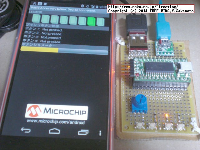
● Android ADK in PIC
WEBに散らばっている制作方法を参考にして作ってみたテスト。
ADKのサンプル自身は、
microchip\mla\v2016_04_27\apps\smartphone\android\aoa_basic_io
に有ります。
・PIC24FJ64GB002ボードを使用した作品例 ADK
以下編集中
DM240415
マイクロチップ Starter Kit for Android PIC24F Ver [DM240415]
PIC24F Accessory Development Starter Kit for Android Part Number: DM240415
The Microchip PIC24F Accessory Development Start Kit for Android™ is a standalone board used for evaluating and developing electronic accessories for Google’s Android operating system for smartphones and tablets. This kit provides all of the tools and resources required to get an accessory developer quickly started on Android devices. The platform provides a library for accessing and talking to Android devices through the accessory framework found in the Android OS versions 2.3.4, 3.1 and later.
● Android Microbridge in PIC
以下編集中
ADKの他に ADB Bridgeも作りましたが接続する Androidによっては相性が有りました。
ADB Bridgeはここを見て作りました。
PICとAndroidとUSB接続する Microbridge/PIC公開!
組み込み用ADB実装のmicrobridgeをUSB搭載PICで使用する
microbridge-pic
microbridge
●書き込み器 PICkit3
以下編集中
2016/10 追記
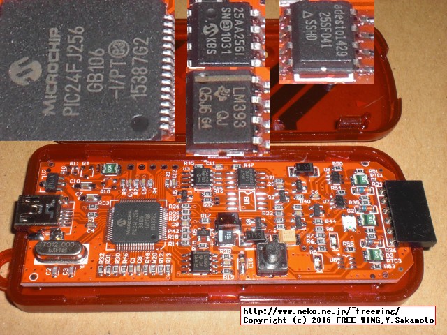
純正の PICkit3は秋月で買っても(4300円から 5700円に値上げ)高いので eBayで購入した PICkit3互換品、ちゃんと認識して使えました。
2016-10-05 22:15:25 +0900 - Completed loading IPE.

*****************************************************

Connecting to MPLAB PICkit 3...

Currently loaded firmware on PICkit 3
Firmware Suite Version.....01.26.26 *
Firmware type..............Midrange

Now Downloading new Firmware for target device: PIC24FJ64GB002
Downloading bootloader
Bootloader download complete
Programming download...
Downloading RS...
RS download complete
Programming download...
Downloading AP...
AP download complete
Programming download...

2016-10-05 22:15:25 +0900 - Completed loading IPE.


*****************************************************

Connecting to MPLAB PICkit 3...

Currently loaded firmware on PICkit 3
Firmware Suite Version.....01.26.26 *
Firmware type..............Midrange

Now Downloading new Firmware for target device: PIC24FJ64GB002
Downloading bootloader
Bootloader download complete
Programming download...
Downloading RS...
RS download complete
Programming download...
Downloading AP...
AP download complete
Programming download...

Currently loaded firmware on PICkit 3
Firmware Suite Version.....01.44.26
Firmware type..............dsPIC33F/24F/24H

Target device was not found (could not detect target voltage VDD). You must connect to a target device to use PICkit 3.

2016-10-05 22:19:12 +0900 - Reading...

*****************************************************

Connecting to MPLAB PICkit 3...

Currently loaded firmware on PICkit 3
Firmware Suite Version.....01.44.26
Firmware type..............dsPIC33F/24F/24H

Target voltage detected
Target device PIC24FJ64GB002 found.
Device ID Revision = 2

The following memory area(s) will be read:
program memory: start address = 0x0, end address = 0xabf7
configuration memory

Reading...
Read complete
2016-10-05 22:19:29 +0900 - Read complete

Target removed
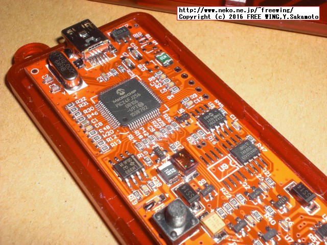
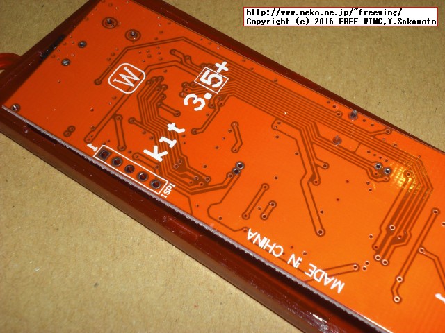
・純正は高いので eBayで購入した PICkit3互換品、ちゃんと認識して使えました
・eBayで購入した PICkit3互換品
・eBayで購入した PICkit3互換品
Tags: [ワンチップCPU]
[HOME]
|
[BACK]
リンクフリー(連絡不要、ただしトップページ以外は Web構成の変更で移動する場合があります)
Copyright (c)
2014-2016 FREE WING,Y.Sakamoto
Powered by 猫屋敷工房 & HTML Generator
http://www.neko.ne.jp/~freewing/cpu/pic_usb_v2/